
Industrial piping in Revit
From P&IDs and point clouds to fabrication deliverables, SmartRouting automates 3D routing and produces bills of materials and isometrics from your piping specifications.
From P&ID to isometric, the data stays consistent.
SmartRouting connects engineering intent, project rules and field reality inside Revit. The designer routes; the platform carries the data, checks every choice and prepares the deliverables.
Start from intent — or the existing plant.
P&ID tags, lines, classes and process data feed the model. For retrofit projects, the point cloud aligns the route with the surveyed installation.
Turn engineering knowledge into rules.
Families describe connections, materials, pressure ratings and SKEYs; the specification defines the permitted components and transitions.
Route in Revit, under control.
The engine calculates the path, inserts compliant fittings and rejects incompatibilities at every connection.
Deliver without rebuilding the data.
Checked lines feed a PCF file that IsoGen or Plant 3D can use to produce fabrication isometrics, bills of materials, PDF and DXF files.
The industrial engineering layer for Revit.
Six layers (process data, specifications, routing engine, Revit, PCF, deliverables) that turn Revit into a complete industrial piping design environment.
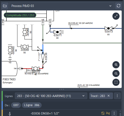
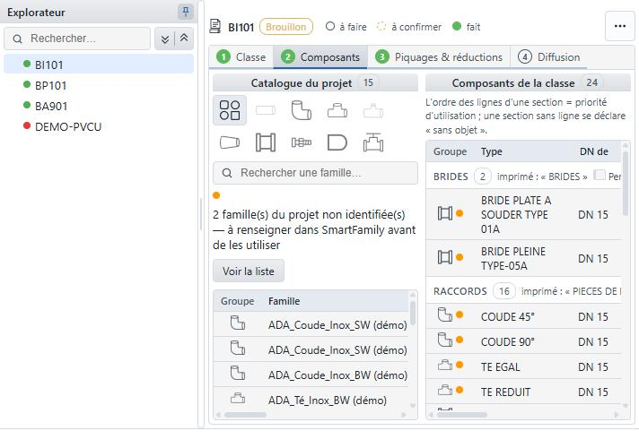
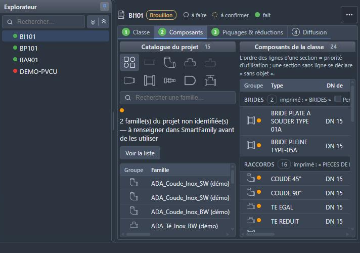
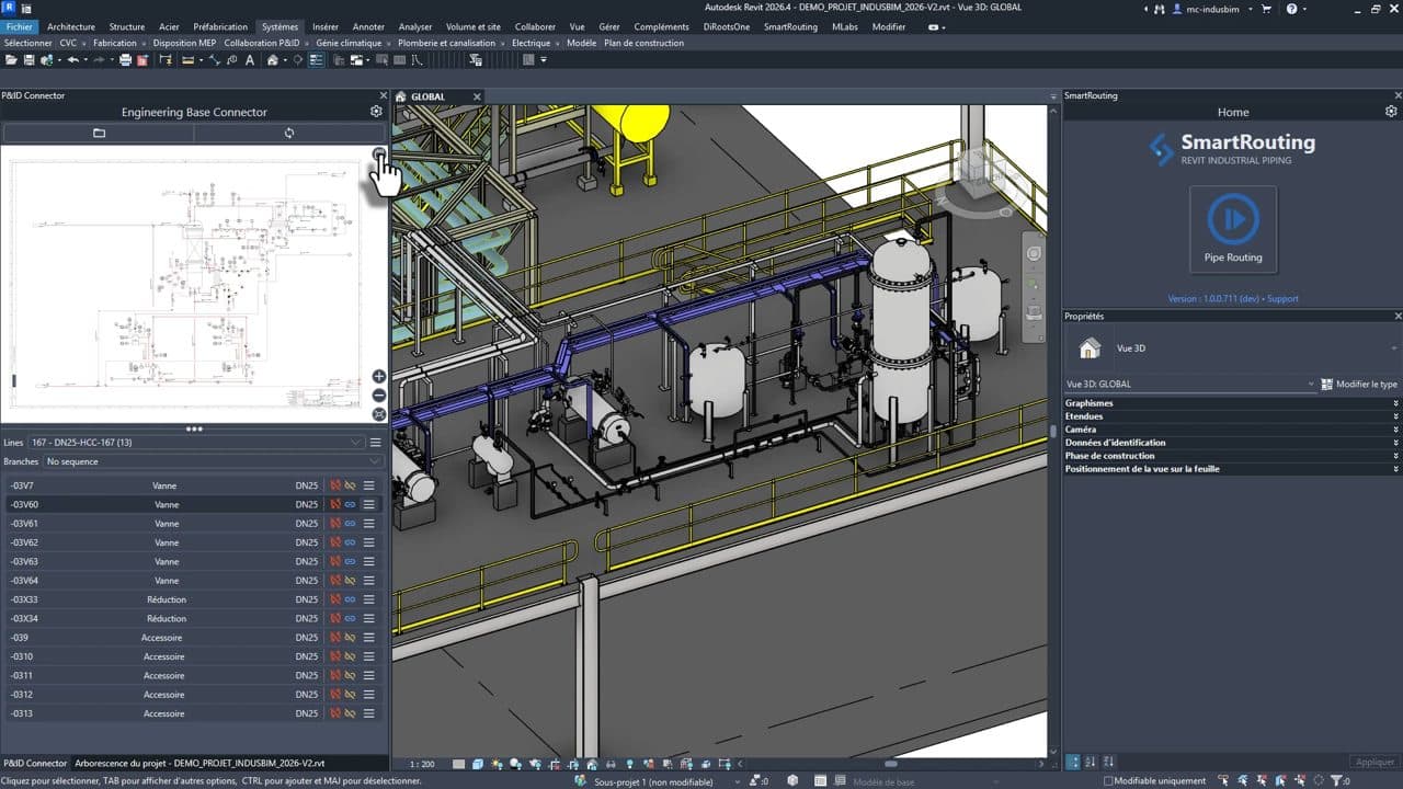
01 · INPUTProcess dataP&ID, line list, equipment and branches, synchronised from Engineering Base.
Lay out, connect and equip your networks in Revit.
SmartRouting lays out piping, ducts and cable trays from a free point, a piece of equipment or an existing network. It calculates a route between two connectors and inserts components in the right place while preserving network properties.
- Draw from scratch, from equipment or from an existing network, inheriting diameter, system and level
- Automatic routing between two connectors, with route previews
- Insert valves and components on a connector or into the middle of a segment
- Selection filtered by the active specification; flanges and reducers added when the connection requires them
- Connect, extend, align, move, copy, cut and check
Pipe drawing and routing
A Revit catalogue the entire workflow can use.
The catalogue manager brings together the categories, families and types loaded in your Revit project. View their geometry and define the engineering properties needed for component placement, piping specifications and deliverables.
- Category → family → type hierarchy and 3D preview
- Material, diameter range and PN / class / SDR pressure rating
- End type for each connector and SKEY for the isometric
Define what each piping class permits.
The specification editor lets you build piping classes from standards data and the project catalogue. Define pipes, permitted components, wall thicknesses, branches and reducers, then share your classes and generate them in Revit.
- Standard, material, grade, diameter range and wall thicknesses for each class
- Permitted component basket, branch matrix and reducer table
- Diameter and SmartInsert filtering; generation of Revit segments, materials and types
Check the line, then produce the isometric.
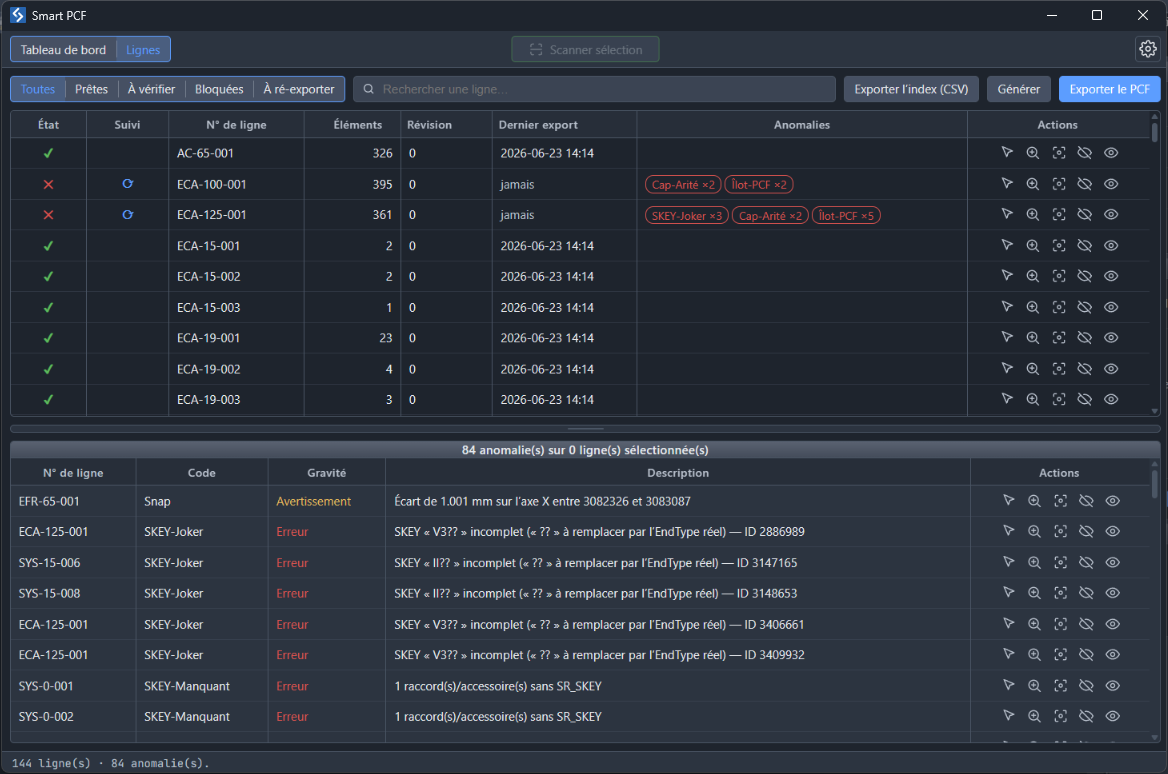
Prepare isometric deliverables from Revit piping lines. Network consistency checks precede the generation of PCF, PDF and DXF files.
- Checks for continuity, connections, line number and required data
- Mapping of Revit families, end types and materials
- Sheet revision and P&ID folio version kept separately
- PCF for Plant 3D / IsoGen; PDF and DXF with SmartIso, currently a prototype
Keep the diagram and model connected.
The P&ID module connects your Revit model to process diagram platforms such as Engineering Base and Plant 3D. Access lines, components and engineering data to guide routing, link modelled elements and check consistency between the diagram and model.
- View folios, lines, components and process data from Revit
- Use diameter, class, service and tags for routing and element assignment
- Identify placed or missing elements and discrepancies between the P&ID and model
Turn an existing-plant survey into a Revit network.
In a 3D view, Point Cloud measures the axis and diameter of an existing pipe, selects the nominal diameter from the pipe type and places the segment in Revit. Surveying continues manually or automatically and remains documented in the project.
- Manual two-point detection or automatic pipe tracking through the point cloud
- Measured diameter, as-built or straightened mode, and insulation allowance
- Connection to the previous segment and a persistent report with quality, direction and diameter
An engineering demonstration on your specification.
A session with an Adalense engineer, on your piping classes and a real case.
Our plans
Choose the features you need. Each row links back to its detailed presentation.
Compatible with Revit 2023 to 2027
| Features Select a feature to return to its explanation. | Essential The essential tools to route, place families and work from existing conditions in Revit. | Premium The complete workflow, from piping specifications and P&ID to isometric deliverables. |
|---|---|---|
| Drawing and routing | Included | Included |
| Catalogue and families | Included | Included |
| Piping specification | Not included | Included |
| Isometric | Not included | Included |
| P&ID | Not included | Included |
| Point Cloud | Included | Included |
| Choose a plan | Select | Select |